You can model the effects of temperature differentials in members and plates. For members, these loads cause the axial expansion or contraction of the member along its length, i.e. axial stress only. The temperature is assumed constant across the member's depth. For plates, these loads cause an in-plane expansion or contraction of the plate. The temperature is assumed constant through the thickness of the plate.
Note
Note
The Coefficient of Thermal Expansion (α) is entered on the Materials spreadsheet. Note that this value is entered per 100,000 degrees (it is sometimes listed per 1,000 degrees).
The joint temperatures recorded on the Joint Coordinates spreadsheet define the ambient thermal state of the structure. Thermal loads, entered as distributed loads on the Distributed Loads spreadsheet, induce axial stress in the member.
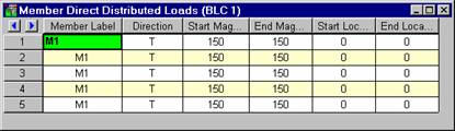
The difference between the applied thermal load and the ambient temperature is the stress inducing temperature.
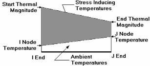
Since you can define start and end locations for the thermal load, you can define up to three separate thermal regions. Interpolating from the I-end temperature to the start thermal load for the first region, from the start thermal load to the end thermal load for the second region and from the end thermal load to the J end temperature for the third region.
The joint temperatures recorded on the Joint Coordinates Spreadsheet define the ambient thermal state of the structure. The joint temperature at the I-end of the member is interpolated across to the J end temperature to define the ambient state of the member. Thermal loads, entered as distributed loads on the Distributed Loads Spreadsheet, induce axial stress in the member. The difference between the applied thermal load and the ambient temperature is the stress inducing temperature.
Thermal forces are calculated thusly:
Ft = A*E*a*ΔT
Where,
Ft = Calculated Thermal Force
A = Member Cross Sectional Area
E = Elastic Modulus
a = Coefficient of Thermal Expansion
ΔT = Stress Inducing Temperature
Thermal loads provide a way to introduce pre-stressing in a model. Given a desired prestress force, just back-solve the thermal force equation for the needed DT. Remember, as the model expands (or contracts), the prestress force may be altered.